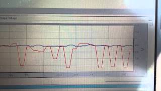
2:05
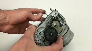
Diagnosing an electric motor with a lab scope
Justin Miller
0:48
Using upstream and downstream oxygen sensors to test the catalytic converter
2:06
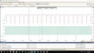
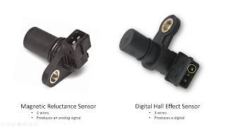
Testing hall effect camshaft or crankshaft sensors
1:09
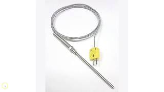
Testing a magnetic reluctance camshaft or crankshaft sensor
3:20
Capturing CAN Bus Data Using a Breakout Box
2:25
7:32
Electricity & Magnetism
2:59
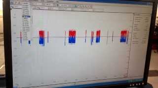
Using a current probe to find a short circuit
16:35
Intro to the PicoScope (Automotive Scope)
5:36
How "Duty Cycling" works to dim a light
3:57
How to make a "relay and fuse" jumper (current loop)
7:35
How to Perform a Relative Compression Test on an Engine
6:28
Testing Fuel Injectors with a Lab Scope
8:29
Decoding CAN Bus Data Using the PicoScope
9:07
Taking Measurements of Your Waveforms in the Pico Scope Software
14:52
Testing a Battery, Starting System, & Charging System Using a Lab Scope
19:38
Camshaft and Crankshaft Position Sensor Waveform Analysis
20:28
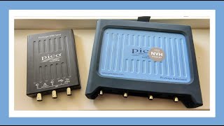
Intro to Pico NVH Diagnostics
9:16
How to Scale a Sensor and Create a Custom Probe
7:33
Setting up 2000 series PicoScope for automotive use
5:37
How to create a 1000 amp current probe in your PicoScope
5:15
Measuring Frequency, Duty Cycle, & Pulse Width
1:33
Measuring RPM with PicoScope 6 Software
4:59
Using the PicoScope Built-in Waveform Generator
3:03
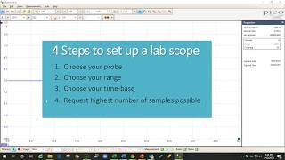
The 4 Steps to Set Up a Lab Scope
6:56
Computer Outputs: High-Side and Low-Side Drivers
13:54
Understanding and Optimizing Sample Rates
1:17
Fixing Pixelated Waveforms
5:55
Using Triggers to Capture Better Waveforms
5:54
Overlaying Multiple Waveforms on the PicoScope (Reference Waveforms)
4:31
Finding CAN Bus Signal Errors
7:23
How Electronic Throttle Actuators Work